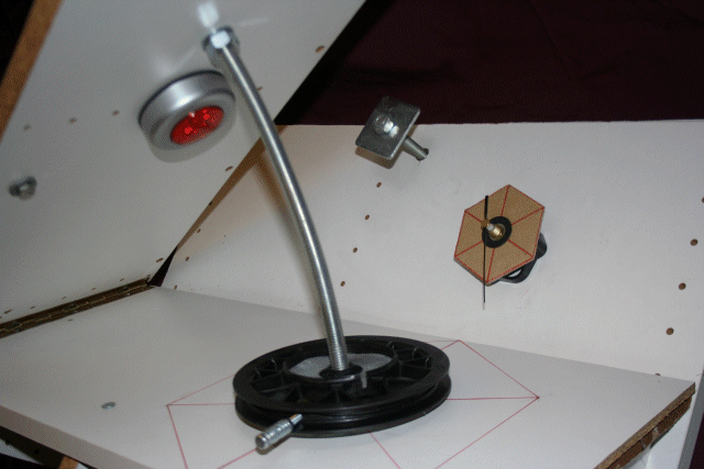
How do you time the rotation ?
 All that is necessary is to turn the Drive Nut at the same rate as the clock (1 rpm). A simple quartz controlled clock mechanism was used with the seconds hand only fitted. The type chosen produces an audible 'tick' once per second.
The clock 'ticks' can thus be counted (in the dark) in sets of 10 and the wheel moved 'by touch', especially if a 'hex sided' guide is fitted (below the drive wheel) which can be felt in the dark.
To make sure no 'ticks' have been missed, a card guide was fitted to the clock, the idea being to check every so often (with a red light torch) that I had not missed any of the 'ticks' and was on the 'correct' segment position
The accuracy aimed at is no worse than 1 second in any group of 10 (non-accumulating).
What's the drive wheel ?
 Initially it was planned to us an old 6" trolley wheel, however an old pulley wheel taken from a broken lawn-mower was found in the 'bits box' and as well as being somewhat larger, was a better fit to the drive nut.
Generally, the larger the wheel the better. The greater the movement needed to make one turn, the easier it will be to judge the angular position (and hence the accuracy achieved) and the smoother the motion of the 'nut' will be.
The Drive Nut was epoxied to the centre of the wheel (as seen in the photo of the pully taken from underneath). On the far right of the wheel a bolt (with washers) is fitted both to make it easier to turn the wheel with minimal vibration and as a turn or 'index' pointer (this was removed when the motor drive was fitted).
Note the wheel chosen for manual drive had to allow a drive belt to be fitted later, for use with a motor drive (a belt is better than gears, since this minimises / eliminates any vibration from the motor). In the case of the trolley wheel, the tyre could be removed allowing the hub to be used directly. The mower pully wheel had to be built up with filler (see later), however it's larger diameter still made it the better choice.
How do you turn it in the dark ?

Whilst the initial plan called for a 'touch sensitive guide' to be laid out on the BarnDoor lower (fixed) arm below the pully wheel, when I started to turn the wheel I found that even the lightest touch to the base arm resulted in unacceptable 'wobble' - and that, in the dark, it was almost impossible to avoid one hand or the other 'bumping into' the screw rod as the wheel was turned 'behind' the rod.
I thus decided to fit a lamp (red light, to avoid loss of your night vision**) and move the wheel 'by eye'.
** note that whilst red light preserves your night vision, it will still ruin your photos. To minimise any chance of reflections getting into the lens, the base and fixed arm should be painted mat black. Further, the camera mount position which was rather too close to the far left edge of the top arm (you can just see the 'silver' nut (back of the mount) to the far left of the lamp, above the hinge, in the photo) had to be moved to a position more directly opposite the lamp.
So much for manual operation - click Next>> (on left) for tips on alignment ...